Proper grounding—often called earthing in many parts of the world—is one of the most overlooked aspects of diesel-generator installation. While it is easy to focus on power capacity, ventilation, or fuel autonomy, the earthing system is the hidden safeguard that quietly protects people, equipment, and buildings from electric shock, lightning strikes, and damaging fault currents. Inadequate grounding can turn a perfectly sized generator into a safety hazard, trigger nuisance trips that interrupt critical loads, or even void your warranty. This article outlines the principles, hardware, and best-practice procedures that Jubaili Bros engineers rely on every day to ensure that every set we supply is as safe as it is reliable.
Why Ground at All?
Grounding creates a deliberate, low-impedance path for fault current to return to source (or dissipate into the soil) so that over-current devices can operate quickly. Without it, an insulation failure or a damaged cable could energise the generator enclosure, transfer lethal voltage to fuel lines or structural steel, or bypass protective relays entirely. A well-designed grounding system provides four indispensable benefits:
- Personnel safety. Touch voltages are held below dangerous thresholds, reducing the risk of electric shock.
- Equipment protection. Surge energy from lightning or switching transients finds a route to earth instead of damaging sensitive AVR boards or PLC I/O.
- Reliable over-current clearing. Circuit-breakers and fuses see enough fault current to trip within milliseconds.
- Electromagnetic compatibility (EMC). A stable reference plane minimises voltage differences that can otherwise create communication errors between controllers.
Codes and Standards at a Glance
The exact legal framework depends on your jurisdiction, but most territories align with international consensus documents such as IEC 60364, BS 7430, IEEE Std 142 (“Green Book”), NFPA 70® (NEC), and local energy-authority guidelines. Jubaili Bros aligns its earthing designs with the stricter of the applicable standards, documenting the selected reference in the project data book to ensure compliance and transparency during inspection.
Key Components of a Generator Earthing System
- Earth electrode. Can be a copper-clad rod, deep well electrode, ring conductor, or mesh grid depending on resistivity and site requirements.
- Main earthing conductor (MEC). A copper strip or bare conductor connecting the generator frame and neutral point to the electrode.
- Bonding jumpers. Links fuel tanks, silencer, day-tank, and canopy to the MEC to maintain equipotential bonding.
- Earth bar / Main earthing terminal (MET). The central connection point for all protective conductors, typically located on the switchboard or skid.
Earthing System Design Process
- Conduct a soil resistivity survey. A Wenner or Schlumberger test identifies whether simple rods suffice or a grid is needed.
- Calculate prospective fault current. Use alternator data to determine fault magnitude and duration. For 400 V systems, this often ranges from 10–20 kA over 100–250 ms.
- Select suitable electrode type. Two 3 m rods spaced apart usually suffice in moderate soils, while poor conductivity may require deep wells or chemical rods.
- Size conductors appropriately. IEC 60364 provides guidelines. For most installations, 25 mm² copper suffices up to 1,000 A fault current; use the adiabatic formula otherwise.
- Route and protect the system. Bury copper strip at least 600 mm deep, avoid sharp bends, and use conduit where conductors rise above grade.
- Terminate and label clearly. Exothermic welding ensures long-term integrity. Label all safety-earth points to discourage tampering.
Special Applications and Variations
- Neutral-to-earth bonding. For standalone generators, bond neutral at the star-point. For grid-parallel units, bond at the main LV panel or transformer, not the generator itself.
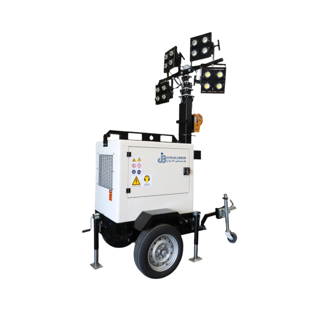
- Mobile sets. Generators above 15 kVA require a temporary earth electrode or mat, unless protected by an RCD ≤30 mA.
- High-rise installations. Roof-top generators must bond to both the lightning down-conductor and the main earth bar in the ground-level LV room. Use low-impedance vertical routes.
Testing and Commissioning
Verify earth resistance using fall-of-potential testing after installation. Results should be recorded in the O&M manual. Acceptable values are up to 5 Ω for standard systems, while critical facilities such as data centres aim for ≤1 Ω. For periodic checks, clamp-on meters offer convenience where multiple return paths exist, though they should be interpreted carefully.
Maintenance and Lifecycle Care
Even a compliant installation can degrade without ongoing care. Common issues include corroded joints, accidental cable cuts, or site expansion that compromises grounding. Jubaili Bros recommends:
- Annual inspections. Check mechanical connections, repaint exposed copper, and tighten fasteners.
- Routine resistance testing. Perform annually for prime-power sets and every two years for standby units.
- Keep a record. Document resistance trends to identify deterioration over time.
- Maintain soil treatment. In dry regions, reapply bentonite or ground-enhancing materials every 5–8 years.
Common Pitfalls to Avoid
- Using water pipes as earth. This is unreliable, especially with modern plastic plumbing replacing metallic runs.
- Ignoring fuel system bonding. Unbonded tanks and sensors can accumulate static and become ignition hazards.
- Assuming uniform soil conditions. Ground resistivity varies greatly across the MENA region; site-specific testing is essential.
- Lack of documentation. Without diagrams and test reports, future troubleshooting becomes difficult.
- Multiple neutral-earth bonds. These can create circulating currents, cause transformer noise, and interfere with fault detection.
The Jubaili Bros Difference
At Jubaili Bros, grounding is not an afterthought. Our engineering teams integrate earthing calculations and layouts during the early design phase, long before civil works begin. During commissioning, we perform witnessed earth-resistance tests and issue detailed hand-over reports. This integrated approach supports our Jubaili Warranty promise: complete ownership of your generator's performance without third-party referrals or delays.
Conclusion
Grounding is a critical safety system that protects people and equipment while ensuring regulatory compliance. Following proven design principles and proactive maintenance keeps your installation safe and operational. If your project requires site-specific grounding advice or formal testing, Jubaili Bros is ready to assist.
Questions? Our technical team would be delighted to support you. Contact Jubaili Bros today.

