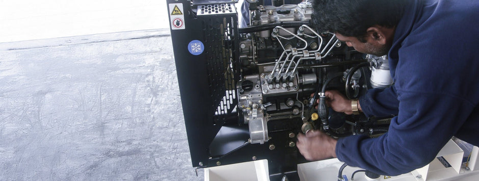
A diesel generator weighing several tonnes imposes significant dynamic forces that travel through floors and adjacent structures. Without a properly designed foundation and vibration-isolation system, those forces lead to cracks, structure-borne noise, misalignment, and early failure of piping and electrical connections. This article outlines how to size a concrete plinth, select the right isolation mounts, and commission the system for quiet, stable, long-term operation.
Why Foundations Matter
Even well-balanced engines produce alternating inertial forces twice per crankshaft revolution. At 1 500 rpm, that equates to 50 Hz—within human hearing range and the structural resonance band of many steel-framed buildings. A heavy, rigid foundation reduces natural frequency, while spring or rubber mounts isolate residual vibration.
Concrete Plinth Design
- Mass guideline: The concrete foundation should weigh 2–3 × the generator's wet weight. A 15-ton generator requires 30–45 tonnes of concrete (concrete density ≈ 2.4 t/m³).
- Dimensions: Extend the plinth 150 mm beyond the generator skid on all sides. Typical height: 300–400 mm.
- Reinforcement: Use #16 rebar at 200 mm spacing in both directions, top and bottom, with 50 mm cover.
- Anchor bolts: Use M24 or M30 bolts set in sleeves; length should be 12 × bolt diameter for secure hold.
- Surface finish: Smooth (CSP 4) but slightly textured to grip isolation pads.
Isolation Mount Options
| Mount Type | Natural Frequency (Hz) | Transmissibility @ 50 Hz | Best For |
|---|---|---|---|
| Rubber-in-shear | 8–12 | 25–30% | < 600 kVA, ground installations |
| Spring mounts | 3–5 | ≤ 10% | Large sets, rooftop or suspended floors |
| Air bellows | 1–3 | < 5% | Labs and sensitive environments |
| Inertia base with springs | 2–4 | < 8% | Indoor sites with occupied floors below |
Isolation efficiency η = 1 − T, where transmissibility T = 1 / √((1 − r²)² + (2ζr)²), and r = operating frequency / natural frequency. For rubber pads, r ≥ √2; for spring mounts, r ≥ 10 at 50 Hz yields >90% isolation.
Selecting Spring Mounts
- Calculate static deflection: δ = W / (k × g), where k = spring rate.
- For a target natural frequency ≤ 4 Hz: δ ≈ g / (2πfₙ)². At 4 Hz, this is ~15 mm deflection.
- Divide total generator weight by the number of mounts and add 25% margin for dynamic loading.
- Choose springs with lateral restraint or neoprene cups to prevent side shift during operation.
Floor Load and Vibration Considerations
Post-tensioned slabs may limit point loads to 20 kN under 200 mm². Use steel base plates to spread the load. For rooftop installations, perform modal analysis to ensure floor natural frequency does not align with generator frequency (50 Hz). Adjust mount spacing or add inertia beams as needed.
Fuel and Exhaust Flexibility
Isolation systems allow vertical motion up to 10–20 mm. To prevent stress on fixed services, specify:
- Braided exhaust bellows: Stainless steel, rated to 16 bar, between turbo and vertical riser.
- Flexible fuel hoses: Dual-wall, swaged fittings, at least 300 mm long, arranged in an "S" curve.
- Coolant joints: Expansion bellows if remote radiators are used.
Installation Procedure
- Allow concrete to cure for a minimum of 28 days before loading.
- Shim mounts to level the generator skid within ±1 mm.
- Tighten anchor bolts to 70% of yield strength, using torque charts per ISO 898-1.
- Measure static deflection with a dial gauge. Ensure mount load is balanced within ±10%.
- Remove transport locking pins (if spring mounts were delivered locked).
- Re-check deflection after 24 hours to account for thermal and settlement effects.
Commissioning and Testing
- Measure vibration velocity on alternator bearings (ISO 10816-6): target ≤ 4.5 mm/s RMS on rigid base.
- Use FFT to verify dominant vibration at crank frequency (25 Hz for 1 500 rpm).
- Compare sound levels with and without isolation. A 3–6 dB(A) drop confirms performance.
Maintenance Guidelines
- Check for spring sag once a year. Replace if permanent set exceeds 15% of original deflection.
- Re-torque anchor bolts during annual service.
- Inspect rubber mounts for oil contamination. Replace if hardness drops >10 Shore A.
- Clear debris from drain holes to prevent water pooling and concrete degradation.
Conclusion
The generator foundation may be hidden beneath the enclosure, but its role is foundational to performance. Correct mass sizing, mount selection, and commissioning help prevent vibration damage, noise complaints, and premature wear. Investing in a sound structural and vibration solution ensures your generator delivers power smoothly, year after year.
Need a foundation or vibration study? Contact Jubaili Bros—our engineers provide dynamic load modelling and prefabricated skid solutions tailored to your site.


